Thursday 24 November 2011

Milling machine


milling machine is a machine tool used to machine solid materials. Milling machines are often classed in two basic forms, horizontal and vertical, which refers to the orientation of the mainspindle. Both types range in size from small, bench-mounted devices to room-sized machines. Unlike a drill press, which holds the workpiece stationary as the drill moves axially to penetrate the material, milling machines also move the workpiece radially against the rotating milling cutter, which cuts on its sides as well as its tip. Workpiece and cutter movement are precisely controlled to less than 0.001 in (0.025 mm), usually by means of precision ground slides and leadscrews or analogous technology. Milling machines may be manually operated, mechanically automated, or digitally automated via computer numerical control (CNC).
Milling machines can perform a vast number of operations, from simple (e.g., slot and keyway cutting, planing, drilling) to complex (e.g., contouring, diesinking). Cutting fluid is often pumped to the cutting site to cool and lubricate the cut and to wash away the resulting swarf.

Types and nomenclature

Mill orientation is the primary classification for milling machines. The two basic configurations are vertical and horizontal. However, there are alternate classifications according to method of control, size, purpose and power source.


Mill orientation


Vertical mill

Vertical milling machine. 1: milling cutter 2: spindle 3: top slide or overarm 4: column 5: table 6: Y-axis slide 7: knee 8: base
In the vertical mill the spindle axis is vertically oriented. Milling cutters are held in the spindle and rotate on its axis. The spindle can generally be extended (or the table can be raised/lowered, giving the same effect), allowing plunge cuts and drilling. There are two subcategories of vertical mills: the bed mill and the turret mill.
  • turret mill has a stationary spindle and the table is moved both perpendicular and parallel to the spindle axis to accomplish cutting. The most common example of this type is the Bridgeport, described below. Turret mills often have a quill which allows the milling cutter to be raised and lowered in a manner similar to a drill press. This type of machine provides two methods of cutting in the vertical (Z) direction: by raising or lowering the quill, and by moving the knee.
  • In the bed mill, however, the table moves only perpendicular to the spindle's axis, while the spindle itself moves parallel to its own axis.
Turret mills are generally considered by some to be more versatile of the two designs. However, turret mills are only practical as long as the machine remains relatively small. As machine size increases, moving the knee up and down requires considerable effort and it also becomes difficult to reach the quill feed handle (if equipped). Therefore, larger milling machines are usually of the bed type.
Also of note is a lighter machine, called a mill-drill. It is quite popular with hobbyists, due to its small size and lower price. A mill-drill is similar to a small drill press but equipped with an X-Y table. These are frequently of lower quality than other types of machines.


Horizontal mill

Horizontal milling machine. 1: base 2: column 3: knee 4 & 5: table (x-axis slide is integral) 6: overarm 7: arbor (attached to spindle)
A horizontal mill has the same sort of xy table, but the cutters are mounted on a horizontal arbor (see Arbor milling) across the table. Many horizontal mills also feature a built-in rotary table that allows milling at various angles; this feature is called a universal table. While endmills and the other types of tools available to a vertical mill may be used in a horizontal mill, their real advantage lies in arbor-mounted cutters, called side and face mills, which have a cross section rather like a circular saw, but are generally wider and smaller in diameter. Because the cutters have good support from the arbor and have a larger cross-sectional area than an end mill, quite heavy cuts can be taken enabling rapid material removal rates. These are used to mill grooves and slots. Plain mills are used to shape flat surfaces. Several cutters may be ganged together on the arbor to mill a complex shape of slots and planes. Special cutters can also cut grooves, bevels, radii, or indeed any section desired. These specialty cutters tend to be expensive. Simplex mills have one spindle, and duplex mills have two. It is also easier to cut gears on a horizontal mill. Some horizontal milling machines are equipped with a power-take-off provision on the table. This allows the table feed to be synchronized to a rotary fixture, enabling the milling of spiral features such as hypoid gears.


Comparative merits

The choice between vertical and horizontal spindle orientation in milling machine design usually hinges on the shape and size of a workpiece and the number of sides of the workpiece that require machining. Work in which the spindle's axial movement is normal to one plane, with an endmill as the cutter, lends itself to a vertical mill, where the operator can stand before the machine and have easy access to the cutting action by looking down upon it. Thus vertical mills are most favored for diesinking work (machining a mold into a block of metal).[1] Heavier and longer workpieces lend themselves to placement on the table of a horizontal mill.
Prior to numerical control, horizontal milling machines evolved first, because they evolved by putting milling tables under lathe-like headstocks. Vertical mills appeared in subsequent decades, and accessories in the form of add-on heads to change horizontal mills to vertical mills (and later vice versa) have been commonly used. Even in the CNC era, a heavy workpiece needing machining on multiple sides lends itself to a horizontal machining center, while diesinking lends itself to a vertical one.

Variant

A miniature hobbyist mill plainly showing the basic parts of a mill.
  • Bed mill This refers to any milling machine where the spindle is on a pendant that moves up and down to move the cutter into the work. These are generally more rigid than a knee mill.
  • Box mill or column mill Very basic hobbyist bench-mounted milling machines that feature a head riding up and down on a column or box way.
  • C-Frame mill These are larger, industrial production mills. They feature a knee and fixed spindle head that is only mobile vertically. They are typically much more powerful than a turret mill, featuring a separate hydraulic motor for integral hydraulic power feeds in all directions, and a twenty to fifty horsepower motor. Backlash eliminators are almost always standard equipment. They use large NMTB 40 or 50 tooling. The tables on C-frame mills are usually 18" by 68" or larger, to allow multiple parts to be machined at the same time.
  • Floor mill These have a row of rotary tables, and a horizontal pendant spindle mounted on a set of tracks that runs parallel to the table row. These mills have predominantly been converted to CNC, but some can still be found (if one can even find a used machine available) under manual control. The spindle carriage moves to each individual table, performs the machining operations, and moves to the next table while the previous table is being set up for the next operation. Unlike other mills, floor mills have movable floor units. A crane drops massive rotary tables, X-Y tables, etc., into position for machining, allowing large and complex custom milling operations.
  • Gantry mill The milling head rides over two rails (often steel tubes) which lie at each side of the work surface.
  • Horizontal boring mill Large, accurate bed horizontal mills that incorporate many features from various machine tools. They are predominantly used to create large manufacturing jigs, or to modify large, high precision parts. They have a spindle stroke of several (usually between four and six) feet, and many are equipped with a tailstock to perform very long boring operations without losing accuracy as the bore increases in depth. A typical bed has X and Y travel, and is between three and four feet square with a rotary table or a larger rectangle without a table. The pendant usually provides between four and eight feet of vertical movement. Some mills have a large (30" or more) integral facing head. Right angle rotary tables and vertical milling attachments are available for further flexibility.
  • Jig borer Vertical mills that are built to bore holes, and very light slot or face milling. They are typically bed mills with a long spindle throw. The beds are more accurate, and the handwheels are graduated down to .0001" for precise hole placement.
  • Knee mill or knee-and-column mill refers to any milling machine whose x-y table rides up and down the column on a vertically adjustable knee. This includes Bridgeports.
  • Planer-style mill Large mills built in the same configuration as planers except with a milling spindle instead of a planing head. This term is growing dated as planers themselves are largely a thing of the past.
  • Ram-type mill This can refer to any mill that has a cutting head mounted on a sliding ram. The spindle can be oriented either vertically or horizontally. In practice most mills with rams also involve swiveling ability, whether or not it is called "turret" mounting. The Bridgeport configuration can be classified as a vertical-head ram-type mill. Van Norman specialized in ram-type mills through most of the 20th century. Since the wide dissemination of CNC machines, ram-type mills are still made in the Bridgeport configuration (with either manual or CNC control), but the less common variations (such as were built by Van Norman, Index, and others) have died out, their work being done now by either Bridgeport-form mills or machining centers.
  • Turret mill More commonly referred to as Bridgeport-type milling machines. The spindle can be aligned in many different positions for a very versatile, if somewhat less rigid machine.


Alternate terminology

A milling machine is often called a mill by machinists. The archaic term miller was commonly used in the 19th and early 20th centuries.
Since the 1960s there has developed an overlap of usage between the terms milling machine and machining center. NC/CNC machining centers evolved from milling machines, which is why the terminology evolved gradually with considerable overlap that still persists. The distinction, when one is made, is that a machining center is a mill with features that pre-CNC mills never had, especially an automatic tool changer (ATC) that includes a tool magazine (carousel), and sometimes an automatic pallet changer (APC). In typical usage, all machining centers are mills, but not all mills are machining centers; only mills with ATCs are machining centers.


Computer numerical control

Thin wall milling of aluminum using a water based cutting fluid on the milling cutter
Most CNC milling machines (also called machining centers) are computer controlled vertical mills with the ability to move the spindle vertically along the Z-axis. This extra degree of freedom permits their use in diesinking, engraving applications, and 2.5D surfaces such as relief sculptures. When combined with the use of conical tools or a ball nose cutter, it also significantly improves milling precision without impacting speed, providing a cost-efficient alternative to most flat-surface hand-engraving work.
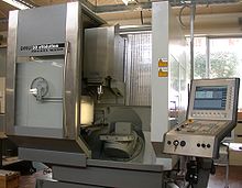
Five-axis machining center with rotating table and computer interface
CNC machines can exist in virtually any of the forms of manual machinery, like horizontal mills. The most advanced CNC milling-machines, the multiaxis machine, add two more axes in addition to the three normal axes (XYZ). Horizontal milling machines also have a C or Q axis, allowing the horizontally mounted workpiece to be rotated, essentially allowing asymmetric and eccentricturning. The fifth axis (B axis) controls the tilt of the tool itself. When all of these axes are used in conjunction with each other, extremely complicated geometries, even organic geometries such as a human head can be made with relative ease with these machines. But the skill to program such geometries is beyond that of most operators. Therefore, 5-axis milling machines are practically always programmed with CAM.
With the declining price of computers and open source CNC software, the entry price of CNC machines has plummeted.
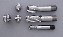
High speed steel with cobalt endmills used for cutting operations in a milling machine.


Tooling

The accessories and cutting tools used on machine tools (including milling machines) are referred to in aggregate by the mass noun "tooling". There is a high degree of standardization of the tooling used with CNC milling machines, and a lesser degree with manual milling machines.
Milling cutters for specific applications are held in various tooling configurations.
CNC milling machines nearly always use SK (or ISO), CAT, BT or HSK tooling. SK tooling is the most common in Europe, while CAT tooling, sometimes called V-Flange Tooling, is the oldest and probably most common type in the USA. CAT tooling was invented by Caterpillar Inc. of Peoria, Illinois, in order to standardize the tooling used on their machinery. CAT tooling comes in a range of sizes designated as CAT-30, CAT-40, CAT-50, etc. The number refers to the Association for Manufacturing Technology (formerly the National Machine Tool Builders Association (NMTB))Taper size of the tool.
A CAT-40 toolholder.
A boring head on a Morse taper shank.
An improvement on CAT Tooling is BT Tooling, which looks similar and can easily be confused with CAT tooling. Like CAT Tooling, BT Tooling comes in a range of sizes and uses the same NMTB body taper. However, BT tooling is symmetrical about the spindle axis, which CAT tooling is not. This gives BT tooling greater stability and balance at high speeds. One other subtle difference between these two toolholders is the thread used to hold the pull stud. CAT Tooling is all Imperial thread and BT Tooling is all Metric thread. Note that this affects the pull stud only, it does not affect the tool that they can hold, both types of tooling are sold to accept both Imperial and metric sized tools.
SK and HSK tooling, sometimes called "Hollow Shank Tooling", is much more common in Europe where it was invented than it is in the United States. It is claimed that HSK tooling is even better than BT Tooling at high speeds. The holding mechanism for HSK tooling is placed within the (hollow) body of the tool and, as spindle speed increases, it expands, gripping the tool more tightly with increasing spindle speed. There is no pull stud with this type of tooling.
For manual milling machines, there is less standardization, because a greater plurality of formerly competing standards exist. Newer and larger manual machines usually use NMTB tooling. This tooling is somewhat similar to CAT tooling but requires a drawbar within the milling machine. Furthermore, there are a number of variations with NMTB tooling that make interchangeability troublesome. The older a machine, the greater the plurality of standards that may apply (e.g.,Morse, Jarno, Brown & Sharpe, Van Norman, and other less common builder-specific tapers). However, two standards that have seen especially wide usage are the Morse #2 and the R8, whose prevalence was driven by the popularity of the mills built by Bridgeport Machines ofBridgeport, Connecticut. These mills so dominated the market for such a long time that "Bridgeport" is virtually synonymous with "manual milling machine". Most of the machines that Bridgeport made between 1938 and 1965 used a Morse taper #2, and from about 1965 onward most used an R8 taper.


Accessories

  • Arbor support
  • Stop block


Wednesday 23 November 2011

Lathe Machine


lathe  is a machine tool which rotates the workpiece on its axis to perform various operations such as cutting, sanding, knurling, drilling, or deformation with tools that are applied to the workpiece to create an object which has symmetry about an axis of rotation.
Lathes are used in woodturning, metalworking, metal spinning, and glassworking. Lathes can be used to shape pottery, the best-known design being the potter's wheel. Most suitably equipped metalworking lathes can also be used to produce most solids of revolution, plane surfaces and screw threads or helices. Ornamental lathes can produce three-dimensional solids of incredible complexity. The material can be held in place by either one or two centers, at least one of which can be moved horizontally to accommodate varying material lengths. Other workholding methods include clamping the work about the axis of rotation using a chuck or collet, or to a faceplate, using clamps or dogs.
Examples of objects that can be produced on a lathe include candlestick holders, gun barrels, cue sticks, table legs, bowls, baseball bats, musical instruments (especiallywoodwind instruments), crankshafts and camshafts.

Parts

Parts of a wood lathe
A lathe may or may not have a stand (or legs), which sits on the floor and elevates the lathe bed to a working height. Some lathes are small and sit on a workbench ortable, and do not have a stand.
Almost all lathes have a bed, which is (almost always) a horizontal beam (althoughCNC lathes commonly have an inclined or vertical beam for a bed to ensure thatswarf, or chips, falls free of the bed). Woodturning lathes specialised for turning large bowls often have no bed or tailstock, merely a free-standing headstock and a cantilevered toolrest.
At one end of the bed (almost always the left, as the operator faces the lathe) is aheadstock. The headstock contains high-precision spinning bearings. Rotating within the bearings is a horizontal axle, with an axis parallel to the bed, called the spindle. Spindles are often hollow, and have exterior threads and/or an interiorMorse taper on the "inboard" (i.e., facing to the right / towards the bed) by which workholding accessories may be mounted to the spindle. Spindles may also have exterior threads and/or an interior taper at their "outboard" (i.e., facing away from the bed) end, and/or may have a handwheel or other accessory mechanism on their outboard end. Spindles are powered, and impart motion to the workpiece.
The spindle is driven, either by foot power from a treadle and flywheel or by a belt or gear drive to a power source. In most modern lathes this power source is an integral electric motor, often either in the headstock, to the left of the headstock, or beneath the headstock, concealed in the stand.
In addition to the spindle and its bearings, the headstock often contains parts to convert the motor speed into various spindle speeds. Various types of speed-changing mechanism achieve this, from a cone pulley or step pulley, to a cone pulley with back gear (which is essentially a low range, similar in net effect to the two-speed rear of a truck), to an entire gear train similar to that of a manual-shift auto transmission. Some motors have electronic rheostat-type speed controls, which obviates cone pulleys or gears.
The counterpoint to the headstock is the tailstock, sometimes referred to as the loose head, as it can be positioned at any convenient point on the bed, by undoing a locking nut, sliding it to the required area, and then relocking it. The tailstock contains a barrel which does not rotate, but can slide in and out parallel to the axis of the bed, and directly in line with the headstock spindle. The barrel is hollow, and usually contains a taper to facilitate the gripping of various type of tooling. Its most common uses are to hold a hardened steel centre, which is used to support long thin shafts while turning, or to hold drill bits for drilling axial holes in the work piece. Many other uses are possible.
Metalworking lathes have a carriage (comprising a saddle and apron) topped with a cross-slide, which is a flat piece that sits crosswise on the bed, and can be cranked at right angles to the bed. Sitting atop the cross slide is usually another slide called a compound rest, which provides 2 additional axes of motion, rotary and linear. Atop that sits a toolpost, which holds a cutting tool which removes material from the workpiece. There may or may not be a lead screw, which moves the cross-slide along the bed.
Woodturning and metal spinning lathes do not have cross-slides, but rather have banjos, which are flat pieces that sit crosswise on the bed. The position of a banjo can be adjusted by hand; no gearing is involved. Ascending vertically from the banjo is a toolpost, at the top of which is a horizontal toolrest. In woodturning, hand tools are braced against the tool rest and levered into the workpiece. In metal spinning, the further pin ascends vertically from the tool rest, and serves as a fulcrum against which tools may be levered into the work piece.


Accessories

A steady rest
Unless a workpiece has a taper machined onto it which perfectly matches the internal taper in the spindle, or has threads which perfectly match the external threads on the spindle (two conditions which rarely exist), an accessory must be used to mount a workpiece to the spindle.
A workpiece may be bolted or screwed to a faceplate, a large, flat disk that mounts to the spindle. In the alternative, faceplate dogs may be used to secure the work to the faceplate.
A workpiece may be mounted on a mandrel, or circular work clamped in a three- or four-jaw chuck. For irregular shaped workpieces it is usual to use a four jaw (independent moving jaws) chuck. These holding devices mount directly to the Lathe headstock spindle.
In precision work, and in some classes of repetition work, cylindrical workpieces are usually held in a collet inserted into the spindle and secured either by a drawbar, or by a collet closing cap on the spindle. Suitable collets may also be used to mount square or hexagonal workpieces. In precision toolmaking work such collets are usually of the draw-in variety, where, as the collet is tightened, the workpiece moves slightly back into the headstock, whereas for most repetition work the dead length variety is preferred, as this ensures that the position of the workpiece does not move as the collet is tightened.
A soft workpiece (wooden) may be pinched between centers by using a spur drive at the headstock, which bites into the wood and imparts torque to it.
Live center (top); dead center (bottom)
A soft dead center is used in the headstock spindle as the work rotates with the centre. Because the centre is soft it can be trued in place before use. The included angle is 60°. Traditionally, a hard dead center is used together with suitable lubricant in the tailstock to support the workpiece. In modern practice the dead center is frequently replaced by a live center, as it turns freely with the workpiece — usually on ball bearings — reducing the frictional heat, especially important at high speeds. When clear facing a long length of material it must be supported at both ends. This can be achieved by the use of a travelling or fixed steady. If a steady is not available, the end face being worked on may be supported by a dead (stationary) half centre. A half centre has a flat surface machined across a broad section of half of its diameter at the pointed end. A small section of the tip of the dead centre is retained to ensure concentricity. Lubrication must be applied at this point of contact and tail stock pressure reduced. A lathe carrier or lathe dog may also be employed when turning between two centers.
In woodturning, one variation of a live center is a cup center, which is a cone of metal surrounded by an annular ring of metal that decreases the chances of the workpiece splitting.
A circular metal plate with even spaced holes around the periphery, mounted to the spindle, is called an "index plate". It can be used to rotate the spindle to a precise angle, then lock it in place, facilitating repeated auxiliary operations done to the workpiece.
Other accessories, including items such as taper turning attachments, knurling tools, vertical slides, fixed and traveling steadies, etc., increase the versatility of a lathe and the range of work it may perform.


Modes of use

When a workpiece is fixed between the headstock and the tailstock, it is said to be "between centers". When a workpiece is supported at both ends, it is more stable, and more force may be applied to the workpiece, via tools, at a right angle to the axis of rotation, without fear that the workpiece may break loose.
When a workpiece is fixed only to the spindle at the headstock end, the work is said to be "face work". When a workpiece is supported in this manner, less force may be applied to the workpiece, via tools, at a right angle to the axis of rotation, lest the workpiece rip free. Thus, most work must be done axially, towards the headstock, or at right angles, but gently.
When a workpiece is mounted with a certain axis of rotation, worked, then remounted with a new axis of rotation, this is referred to as "eccentric turning" or "multi axis turning". The result is that various cross sections of the workpiece are rotationally symmetric, but the workpiece as a whole is not rotationally symmetric. This technique is used for camshafts, various types of chair legs.


Varieties

The smallest lathes are "jewelers lathes" or "watchmaker lathes", which are small enough that they may be held in one hand. The workpieces machined on a jeweler's lathes are metal, jeweler's lathes can be used with hand-held "graver" tools or with compound rests that attach to the lathe bed. Graver tools are generally supported by a T-rest, not fixed to a cross slide or compound rest. The work is usually held in a collet. Common spindle bore sizes are 6 mm, 8 mm and 10 mm. The term W/W refers to the Webster/Whitcomb collet and lathe, invented by the American Watch Tool Company of Waltham, Massachusetts. Most lathes commonly referred to as watchmakers lathes are of this design. In 1909, the American Watch Tool company introduced the Magnus type collet (a 10-mm body size collet) using a lathe of the same basic design, the Webster/Whitcomb Magnus. (F.W.Derbyshire, Inc. retains the trade names Webster/Whitcomb and Magnus and still produces these collets.) Two bed patterns are common: the WW (Webster Whitcomb) bed, a truncated triangular prism (found only on 8 and 10 mm watchmakers' lathes); and the continental D-style bar bed (used on both 6 mm and 8 mm lathes by firms such as Lorch and Star). Other bed designs have been used, such a triangular prism on some Boley 6.5 mm lathes, and a V-edged bed on IME's 8 mm lathes.
Smaller metalworking lathes that are larger than jewelers' lathes and can sit on a bench or table, but offer such features as tool holders and a screw-cutting gear train are called hobby lathes, and larger versions, "bench lathes". Even larger lathes offering similar features for producing or modifying individual parts are called "engine lathes". Lathes of these types do not have additional integral features for repetitive production, but rather are used for individual part production or modification as the primary role.
Lathes of this size that are designed for mass manufacture, but not offering the versatile screw-cutting capabilities of the engine or bench lathe, are referred to as "second operation" lathes.
Lathes with a very large spindle bore and a chuck on both ends of the spindle are called "oil field lathes".
Fully automatic mechanical lathes, employing cams and gear trains for controlled movement, are called screw machines.
Lathes that are controlled by a computer are CNC lathes.
Lathes with the spindle mounted in a vertical configuration, instead of horizontal configuration, are called vertical lathes or vertical boring machines. They are used where very large diameters must be turned, and the workpiece (comparatively) is not very long.
A lathe with a cylindrical tailstock that can rotate around a vertical axis, so as to present different tools towards the headstock (and the workpiece) are turret lathes.
A lathe equipped with indexing plates, profile cutters, spiral or helical guides, etc., so as to enable ornamental turning is an ornamental lathe.
Various combinations are possible: for example, a vertical lathe have CNC as well (such as a CNC VTL).
Lathes can be combined with other machine tools, such as a drill press or vertical milling machine. These are usually referred to ascombination lathes.


Major categories
]

Woodworking lathes

A modern woodworking lathe.
Woodworking lathes are the oldest variety. All other varieties are descended from these simple lathes. An adjustable horizontal metal rail - the tool rest - between the material and the operator accommodates the positioning of shaping tools, which are usually hand-held. With wood, it is common practice to press and slide sandpaper against the still-spinning object after shaping to smooth the surface made with the metal shaping tools.
There are also woodworking lathes for making bowls and plates, which have no horizontal metal rail, as the bowl or plate needs only to be held by one side from a metal face plate. Without this rail, there is very little restriction to the width of the piece being turned. Further detail can be found on the woodturning page.


Metalworking lathes

A CNC metalworking lathe
In a metalworking lathe, metal is removed from the workpiece using a hardened cutting tool, which is usually fixed to a solid moveable mounting, either a toolpost or a turret, which is then moved against the workpiece using handwheels and/or computer controlled motors. These (cutting) tools come in a wide range of sizes and shapes depending upon their application. Some common styles are diamond, round, square and triangular.
The toolpost is operated by leadscrews that can accurately position the tool in a variety of planes. The toolpost may be driven manually or automatically to produce the roughing and finishing cuts required to turn the workpiece to the desired shape and dimensions, or for cutting threads, worm gears, etc. Cutting fluid may also be pumped to the cutting site to provide cooling, lubrication and clearing of swarf from the workpiece. Some lathes may be operated under control of a computer for mass production of parts (see "Computer Numerical Control").
Manually controlled metalworking lathes are commonly provided with a variable ratio gear train to drive the main leadscrew. This enables different thread pitches to be cut. On some older lathes or more affordable new lathes, the gear trains are changed by swapping gears with various numbers of teeth onto or off of the shafts, while more modern or expensive manually controlled lathes have a quick change box to provide commonly used ratios by the operation of a lever. CNC lathes use computers and servomechanisms to regulate the rates of movement.
On manually controlled lathes, the thread pitches that can be cut are, in some ways, determined by the pitch of the leadscrew: A lathe with ametric leadscrew will readily cut metric threads (including BA), while one with an imperial leadscrew will readily cut imperial unit based threads such as BSW or UTS (UNF,UNC). This limitation is not insurmountable, because a 127-tooth gear, called a transposing gear, is used to translate between metric and inch thread pitches. However, this is optional equipment that many lathe owners do not own. It is also a larger changewheel than the others, and on some lathes may be larger than the changewheel mounting banjo is capable of mounting.
The workpiece may be supported between a pair of points called centres, or it may be bolted to a faceplate or held in a chuck. A chuck has movable jaws that can grip the workpiece securely.
There are some effects on material properties when using a metalworking lathe. There are few chemical or physical effects, but there are many mechanical effects, which include residual stress, microcracks, workhardening, and tempering in hardened materials.


Cue lathes

Cue lathes function similar to turning and spinning lathes allowing for a perfectly radially-symmetrical cut for billiard cues. They can also be used to refinish cues that have been worn over the years.


Glass working lathes

Glassworking lathes are similar in design to other lathes, but differ markedly in how the workpiece is modified. Glassworking lathes slowly rotate a hollow glass vessel over a fixed or variable temperature flame. The source of the flame may be either hand-held, or mounted to a banjo/cross slide that can be moved along the lathe bed. The flame serves to soften the glass being worked, so that the glass in a specific area of the workpiece becomes malleable, and subject to forming either by inflation ("glassblowing"), or by deformation with a heat resistant tool. Such lathes usually have two headstocks with chucks holding the work, arranged so that they both rotate together in unison. Air can be introduced through the headstock chuck spindle for glassblowing. The tools to deform the glass and tubes to blow (inflate) the glass are usually handheld.
In diamond turning, a computer-controlled lathe with a diamond-tipped tool is used to make precision optical surfaces in glass or other optical materials. Unlike conventional optical grinding, complex aspheric surfaces can be machined easily. Instead of the dovetailed ways used on the tool slide of a metal turning lathe, the ways typically float on air bearings and the position of the tool is measured by optical interferometry to achieve the necessary standard of precision for optical work. The finished work piece usually requires a small amount subsequent polishing by conventional techniques to achieve a finished surface suitably smooth for use in a lens, but the rough grinding time is significantly reduced for complex lenses.


Metal spinning lathes

In metal spinning, a disk of sheet metal is held perpendicularly to the main axis of the lathe, and tools with polished tips (spoons) are hand held, but levered by hand against fixed posts, to develop large amounts of torque/pressure that deform the spinning sheet of metal.
Metal spinning lathes are almost as simple as woodturning lathes (and, at this point, lathes being used for metal spinning almost always arewoodworking lathes). Typically, metal spinning lathes require a user-supplied rotationally symmetric mandrel, usually made of wood, which serves as a template onto which the workpiece is moulded (non-symmetric shapes can be done, but it is a very advanced technique). For example, if you want to make a sheet metal bowl, you need a solid chunk of wood in the shape of the bowl; if you want to make a vase, you need a solid template of a vase, etc.
Given the advent of high speed, high pressure, industrial die forming, metal spinning is less common now than it once was, but still a valuable technique for producing one-off prototypes or small batches where die forming would be uneconomical.


Ornamental turning lathes

The ornamental turning lathe was developed around the same time as the industrial screwcutting lathe in the nineteenth century. It was used not for making practical objects, but for decorative work - ornamental turning. By using accessories such as the horizontal and vertical cutting frames, eccentric chuck and elliptical chuck, solids of extraordinary complexity may be produced by various generative procedures.
A special purpose lathe, the Rose engine lathe is also used for ornamental turning, in particular for engine turning, typically in precious metals, for example to decorate pocket watch cases. As well as a wide range of accessories, these lathes usually have complex dividing arrangements to allow the exact rotation of the mandrel. Cutting is usually carried out by rotating cutters, rather than directly by the rotation of the work itself. Because of the difficulty of polishing such work, the materials turned, such as wood or ivory, are usually quite soft, and the cutter has to be exceptionally sharp. The finest ornamental lathes are generally considered to be those made by Holtzapffel around the turn of the 19th century.


Reducing lathe

Many types of lathes can be equipped with accessory components to allow them to reproduce an item: the original item is mounted on one spindle, the blank is mounted on another, and as both turn in synchronized manner, one end of an arm "reads" the original and the other end of the arm "carves" the duplicate.
reducing lathe is a specialized lathe that is designed with this feature, and which incorporates a mechanism similar to a pantograph, so that when the "reading" end of the arm reads a detail that measures one inch (for example), the cutting end of the arm creates an analogous detail that is (for example) one quarter of an inch (a 4:1 reduction, although given appropriate machinery and appropriate settings, any reduction ratio is possible).
Reducing lathes are used in coin-making, where a plaster original (or an epoxy master made from the plaster original, or a copper shelled master made from the plaster original, etc.) is duplicated and reduced on the reducing lathe, generating a master die.


Rotary lathes

A lathe in which softwood, like spruce or pine, or hardwood, like birch, logs are turned against a very sharp blade and peeled off in one continuous or semi-continuous roll. Invented by Immanuel Nobel (father of the more famous Alfred Nobel). The first such lathes were set up in the United States in the mid-19th century. The product is called wood veneer and it is used for finishing chipboard objects and makingplywood.


Watchmaker's lathes

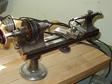
Watchmaker's lathe
Watchmakers lathes are delicate but precise metalworking lathes, usually without provision forscrewcutting, and are still used by horologists for work such as the turning of balance shafts. A handheld tool called a graver is often used in preference to a slide mounted tool. The original watchmaker's turns was a simple dead-centre lathe with a moveable rest and two loose headstocks. The workpiece would be rotated by a bow, typically of horsehair, wrapped around