Wednesday 25 April 2012

General Recommendations for Milling Operations


                   General Recommendations for Milling Operations
         
          Troubleshooting Guide for Milling Operations
            
             Machined Surface Features in Face Milling


            Figure 24.13  Machined surface features in face milling.  See also Fig. 24.6.
 
 
                        Edge Defects in Face Milling
      Figure 24.14  Edge defects in face milling:  (a)  burr formation along workpiece edge, (b)   breakout along workpiece edge, and (c) how it can be avoided by increasing the lead angle (see also last row in Table 24.4).


Milling Cutter

Face-Milling Cutter with Index able Inserts

Figure 24.5  A face-milling cutter with index able inserts.  Source:  Courtesy of Ingersoll Cutting Tool Company. 

Effect of Insert Shape on Feed Marks on a Face-Milled Surface

Figure 24.6  Schematic illustration of the effect of insert shape on feed marks on a face-milled surface:
 (a)  small corner radius, 
 (b) corner flat on insert, and 
 (c) wiper, consisting of small radius followed by a large radius which leaves   smoother feed marks.   
 (d)  Feed marks due to various insert shapes. 

            Face-Milling Cutter

        
                    Figure 24.7  Terminology for a face-milling cutter.
      Effect of Lead Angle on Undeformed Chip Thickness in Face Milling

Figure 24.8  The effect of the lead angle on the undeformed chip thickness in face milling.  Note that as the lead angle increases, the chip thickness decreases, but the length of contact (i.e., chip width) increases.  The edges of the insert must be sufficiently large to accommodate the contact length increase.
 
   Position of Cutter and Insert in Face Milling
Figure 24.9  (a)  Relative position of the cutter and insert as it first engages the workpiece in face milling.
(b)  Insert positions towards the end of cut.
     (c)  Examples of exit angles of insert, showing desirable (positive or negative angle) and undesirable (zero angle) positions.  In all figures, the cutter spindle is perpendicular to the page and rotates clockwise.

                 
                   Ball Nose End Mills

Figure 24.10  Ball nose end mills.  These cutters are able to produce elaborate contours and are often used in the machining of dies and molds.  (See also Fig. 24.2d.)  Source:  Courtesy of Dijet, Inc. 
                                Cutters
    Figure 24.11  Cutters for (a) straddle milling, (b) form milling, (c) slotting, and (d) slitting with a milling cutter. 
            
               T-Slot Cutting and Shell Mill
               Figure 24.12  (a)  T-slot cutting with a milling cutter.  (b)  A shell mill.

Machining Processes

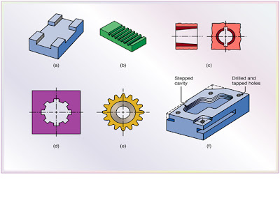
Machining Processes Used to Produce
Various Shapes:  Milling, Broaching, Sawing, and Filing; Gear Manufacturing .
Parts Made with Machining Processes 
Milling Cutters and Milling Operations


Figure 24.2  Some basic types of milling cutters and milling operations.  (a)  Peripheral milling. 
(b)  Face milling.  (c) 
End milling.  (d)
  Ball-end mill with index able coated-carbide inserts machining a cavity in a die block.
 (e)  Milling a sculptured surface with an end mill, using a five-axis numerical control machine.  Source:
 (d)  Courtesy of Iscar.  (e)  Courtesy of The Ingersoll Milling Machine Co.
Milling Operations

Figure 24.3  (a)  Schematic illustration of conventional milling and climb milling.  (b)  lab-milling operation showing depth-of-cut, d; feed per tooth, f; chip depth-of-cut, tc; and workpiece speed, v
(c)  Schematic illustration of cutter travel distance, lc, to reach full depth-of-cut.
Face-Milling Operation


Figure 24.4  Face-milling operation showing (a) action of an insert in face milling; (b) climb milling; (c) conventional milling; (d) dimensions in face milling.  The width of cut, w, is not necessarily the same as the cutter radius.


         Summary of Peripheral Milling Parameters and Formulas

Thursday 19 April 2012

Parts of UH Milling Machine


Universal Horizontal Milling Machine


Milling Machine Parts
         Base
         Gives support and rigidity to machine.
         Acts as reservoir for cutting fluids.
         Column face
         Precision-machined and scraped section used to support and guide. knee when moved vertically.
         Knee
         Houses feed mechanism.
         Attached to column face and moved vertically.
         Saddle
         On top of knee
         Moved in or out by
   Means of cross feed hand wheel (manually or automatically)
         Swivel table housing
         Fastened to saddle on universal milling machine.
         Enables table to be swiveled 45º either side of centerline
         Table
         Rests on guide ways in saddle and travels left and right
         Supports vise and work
         Cross feed hand wheel
         Used to move table in and out
         Table hand wheel
         Used to move table left and right
         Feed dial
         Used to regulate table feeds
         Spindle
         Provides drive for attachments, arbors, cutters
         Over arm
         Provides for correct alignment and support of arbor and various attachments
         Can be adjusted and locked in various positions.
         Arbor support
         Fitted to over arm and can be clamped
         Aligns and supports various  attachments
         Elevating screw
         Gives upward or downward movement to knee and table (manually or automatically)
         Spindle speed dial
         Set by crank used to regulate spindle speed.

Backlash Eliminator
         Eliminates backlash (play) between nut and table lead screw
       Permits operation of climb (down) milling
       Two independent nuts mounted on lead screw
       Nuts engage common crown gear which meshes with rack
       Axial movement of rack controlled by backlash eliminator engaging knob on front of saddle
       Turning knob in, nuts forced to move along lead screw in opposite directions

     Machine Backlash Eliminator

Milling Machines


Horizontal Milling Machines
Manufacturing-type
Cutter height is controlled by vertical movement of headstock
2. Special-type
•   Designed for specific milling operations
3.  Knee-and-column-type
•   Relationship between cutter height and work controlled by vertical movement of         table.
Manufacturing-Type
Used primarily for quantity production of identical parts Distinctive features
Automatic cycle of cutter and work approach
Rapid movement during non-cutting cycle
Automatic spindle stop.
Manufacturing-Type
Two common types
Plain manufacturing type
Small plain automatic knee and column type.
Plain Manufacturing Type Milling Machine


Special-Type Machines 
Designed for individual milling operations. Used for only one particular type of job.
Completely automatic
Employed when hundreds or thousands of similar pieces are to be machined.
Machining Centers
Capable of handling wide variety of work all in one setup.
Straight and contour milling, drilling, reaming, tapping, and boring
Capable of high production rates while still maintaining high degree of accuracy.
Rugged construction, reliable controls
Anti-backlash ball screws.
Knee-and-Column-Type
Milling Machines
Machines in this class fall into three categories: Plain horizontal milling machine.
Universal horizontal milling machines.
Vertical milling machines.
Universal Horizontal
Milling Machines
         Difference from plain horizontal machine is addition of table swivel housing.
         Located between table and saddle.
         Permits table to be swiveled 45º in either direction in a horizontal plane.
       Used for milling of helical grooves in twist drills, milling cutters, and gears.